

4 Bar Linkage Exercise
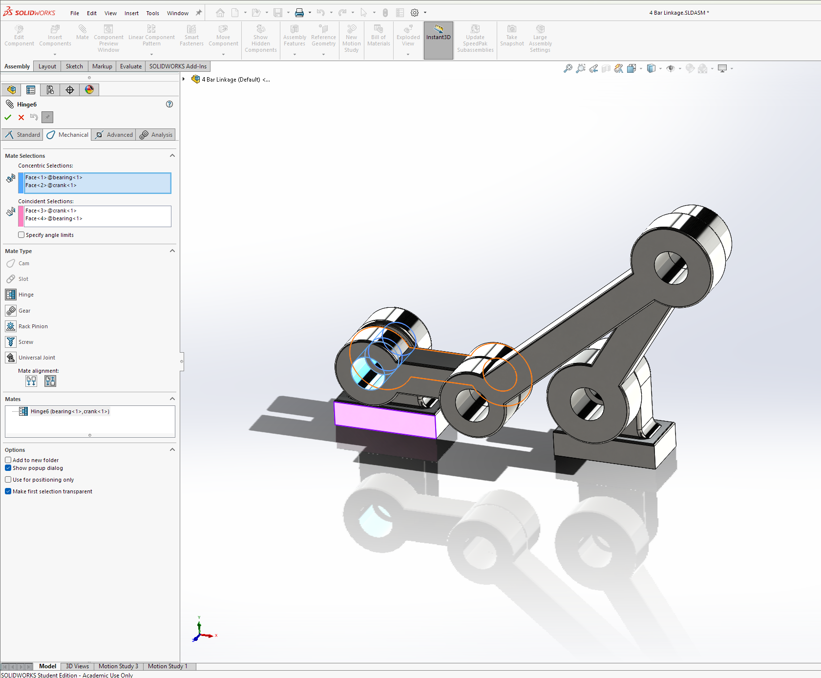
Early in the semester we used SolidWorks to put together a simple four bar linkage assembly in order to explore how we can use motion analyses to determine reaction forces, motor torque, and power consumption to inform hypothetical design parameters. We focused on:
Using hinge, coincident, and concentric mates to put together components
Identifying and replacing redundant mates using Gruebler count (DOF) analysis
Simulating component motion and exporting force, torque, and power plots
Assignment Answers:
a) The maximum value of the motor torque
Tmax = 131.2264N-m
b) The angle of the crank for which the motor torque is maximum in each cycle
Theta @ Tmax = 0 deg
c) The maximum vertical force exerted on Bearing and NewBearing
Bearing FmaxY = 1.87468N, NewBearing FmaxY = 2.33628N
d) The minimum motor power required to have to move the Crank at a constant angular speed
of 600 rpm.
Pmax, measured = Pmin, operational = 0.149607W
e) Explain the meaning of the negative motor torque values and how they are related to the
motion of the mechanism links.
Since gravity applies to the mechanism, negative motor torque values correspond to mechanism link positions that apply a net force to the motor in the direction of motion at a given time.